Thermal Shock Testing for Aerospace and Automotive Electronics
Electronic assemblies rarely fail because of a single, steady temperature. They fail because temperature changes fast — and because two materials bonded together expand at different rates. Thermal shock testing exists to expose that weakness in the laboratory rather than in the field.
This article explains the physics behind thermal shock, the standards that govern it, and the practical points engineers should weigh when specifying a chamber.
What Thermal Shock Actually Tests
A thermal shock test moves a device under test (DUT) between two temperature extremes in a short time, usually by transferring the DUT between a hot zone and a cold zone rather than by ramping a single chamber. The intent is to impose a steep thermal gradient across the assembly.
Because different materials have different coefficients of thermal expansion (CTE), a rapid change in temperature causes differential strain at every interface: solder joints, wire bonds, die attach, potting compounds, connector pins, and housing seals. Repeated cycling accumulates damage through fatigue until a crack initiates.
Two mechanisms matter most:
- CTE mismatch fatigue — the dominant failure mode for solder joints and bond wires.
- Thermal gradient stress — a fast surface-to-core gradient can warp or crack substrates, glass seals, and ceramic packages.
This is why thermal shock is distinct from a slow temperature cycling test. Both are useful, but they stress different things. A slow ramp test is better at revealing creep and diffusion-driven wear-out; a shock test is better at revealing brittle fracture and interfacial delamination.
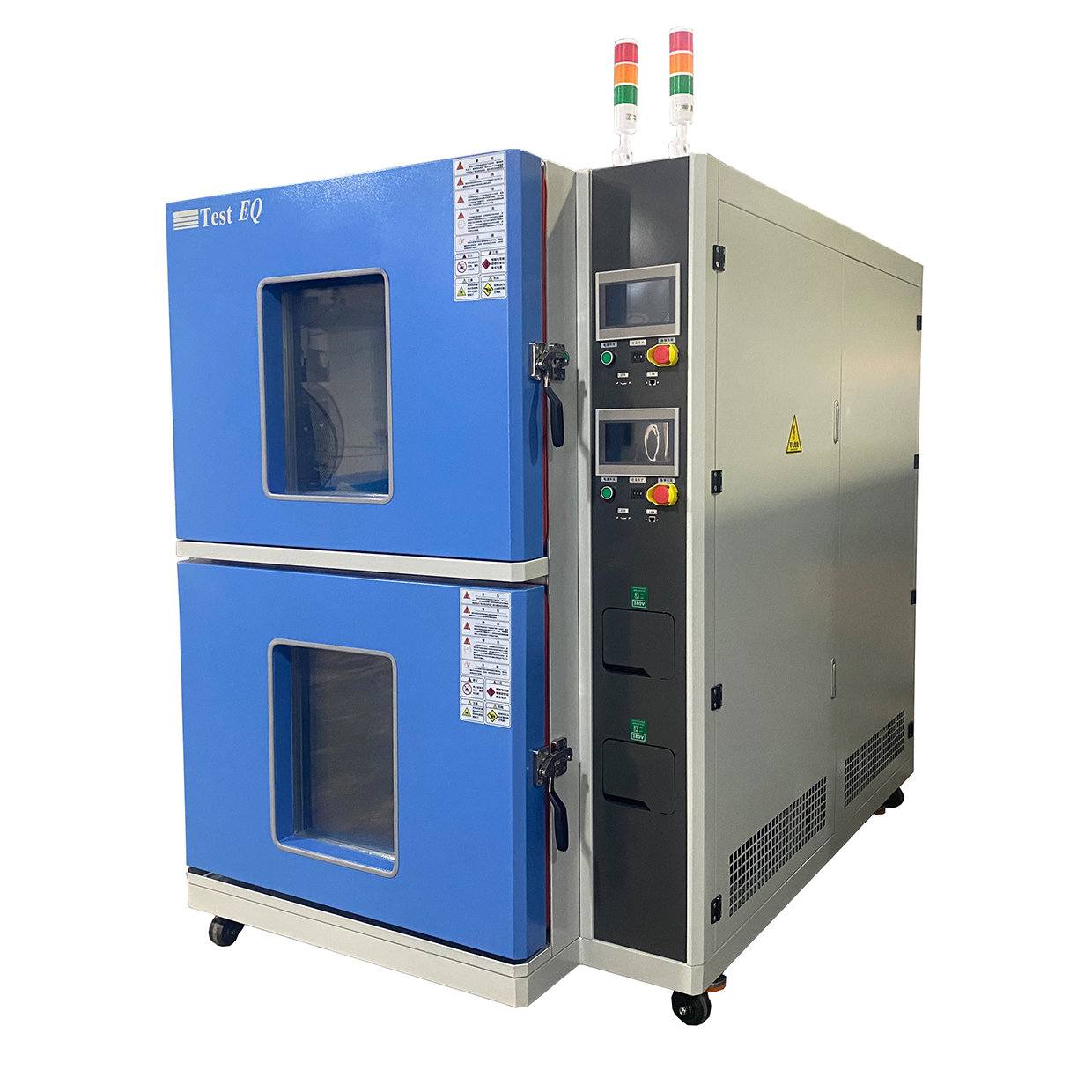
Standards That Define the Test
Most programs reference one or more of the following. The exact profile — soak time, transfer time, dwell, number of cycles — should always come from the governing specification, not from the chamber vendor.
- IEC 60068-2-14 — the base international standard for change of temperature, including both gradual and shock methods (Na, Nb, Nc).
- MIL-STD-810 — environmental engineering considerations and laboratory testing, widely used in defense and aerospace programs.
- GJB 150A — the Chinese military environmental test series, frequently referenced for domestic aerospace and defense work.
- JEDEC JESD22-A104 — temperature cycling for semiconductor devices, with defined profiles for component-level qualification.
- IEC 60068-2-1 / -2-2 — cold and dry heat, often run alongside shock as part of a broader qualification plan.
- ASTM and UL — material and product-level standards that may call out thermal shock as one condition among many.
A common point of confusion: air-to-air shock, liquid-to-liquid shock, and two-chamber versus three-chamber designs all produce different transfer characteristics. Two-chamber systems move the basket between a hot and a cold chamber; three-chamber systems keep a separate ambient dwell position. The choice affects recovery time and how closely you can hold the specified profile.
Aerospace and Automotive: Different Drivers, Same Physics
Aerospace electronics see extreme ambient swings — ground soak at high temperature, rapid ascent to cold soak at altitude, and radiant heating during descent. Avionics line-replaceable units, satellite components, and payload electronics are typically qualified to MIL-STD-810 or equivalent, with shock testing used to screen for workmanship defects before flight. Low-pressure and thermal vacuum conditions often accompany the temperature profile, which is why altitude and thermal vacuum chambers are frequently part of the same qualification flow.
Automotive electronics face a different but equally harsh profile. Under-hood modules cycle between cold soak and engine-bay heat on every drive cycle. Cabin electronics see solar loading. Power electronics for traction and battery management see steep self-heating gradients on top of ambient swings. Automotive qualification frameworks typically combine temperature shock with humidity, vibration, and voltage extremes.
In both industries, the goal is the same: find the weak interface before the customer does. Screening at the component and module level is far cheaper than a field return.
Practical Selection Points
When specifying a thermal shock chamber, these are the questions that most often determine whether the equipment actually fits the program.
Temperature range and recovery. A wide range such as -75 °C to +200 °C covers most aerospace and automotive requirements. What matters more than the setpoint is recovery time — how fast the DUT returns to the specified temperature after transfer. Slow recovery stretches every cycle and can invalidate the profile.
Transfer mechanism and dwell. Basket transfer time, dwell duration, and whether the DUT is powered and monitored during the test all affect results. Many programs require in-situ electrical monitoring to catch intermittent opens as they occur.
Load mass and fixturing. A chamber rated for a given recovery time at no load will behave differently with a heavy fixture and a populated DUT. Always specify recovery at the actual load.
Air versus liquid. Air-to-air is the common choice for boards and modules. Liquid-to-liquid is used where an even faster gradient is required, typically at component level.
Integration with other stresses. If the qualification plan includes vibration or humidity, a combined temperature-humidity-vibration chamber or a temperature-humidity-altitude chamber may reduce handling and improve repeatability compared with running separate tests.
Standards compliance and traceability. Confirm the chamber’s control and monitoring system can produce the records your quality system requires, and that calibration is traceable. ISO 9001 processes at the supplier level are a reasonable baseline indicator of consistency.
For teams mapping out a full qualification flow, it helps to look at the test sequence as a system rather than a list of individual tests. Our applications section outlines how temperature, humidity, altitude, vibration, and corrosion stresses are typically combined across aerospace, automotive, semiconductor, and battery programs, and the projects section shows the equipment categories that support each stage. If you are still defining the profile itself, the tech notes cover the underlying measurement and control principles, and the solutions pages group equipment by test objective rather than by product name.
Summary
Thermal shock testing is a fatigue test disguised as a temperature test. The temperature extremes matter, but the transfer speed, recovery time, dwell, and load conditions determine whether the test actually reproduces the failure mode you care about. Start from the governing standard, define the profile at the real load, and choose equipment based on recovery performance rather than headline range alone. For aerospace and automotive programs, treating thermal shock as one node in a connected qualification flow — alongside humidity, altitude, vibration, and corrosion — produces more useful data than running each stress in isolation.
Questions about matching a chamber to a specific standard or profile? Reach out through our contact page and our engineers can walk through the requirements with you.